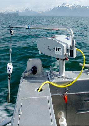
The purpose of an inductive modem system is to retrieve data from the instrument without the need for a sophisticated underwater cable. Instead, a low-frequency signal is generated in the jacketed steel mooring cable (green cable in photo) and seawater is used as return ground. The communication to the topside device is handled with the Seabird inductive modem whereas support for the IMM communication protocol and transfer of data from the Aquadopp to the IMM is provided by a special version of the Aquadopp firmware.
On the outside, the inductive modem coupler appears as a mechanical modification to the standard Aquadopp end-cap. The system is composed of several parts:

- Inside the Aquadopp, the Seabird IMM board is located on top of an interface board that ensures the communication between the Aquadopp electronics and between the IMM board and the inductive coil that clamps around the cable. The board is seamlessly integrated with Aquadopp electronics and can be an upgrade to any Aquadopp shipped after the summer of 2008 (firmware version 3.xx and above).
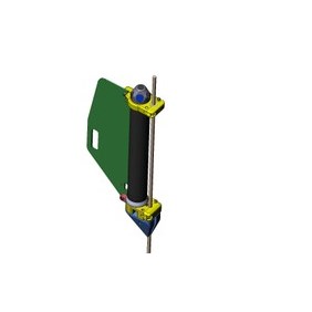
- A special end-cap that includes the coil that goes around the cable (bottom yellow part in the drawing)
- A clamping system that holds the Aquadopp rigidly attached to the wire (upper yellow part)
- A fin (green in drawing) that is designed to ensure that the Aquadopp is stable even if the ocean current is strong. The fin is designed to be used both with short (single-battery) and standard (double-battery) Aquadopp canisters
- A fishing line rejector (bottom blue part on the bottom) that allows fishing lines and nets to glide up along the mooring cable without attaching to the Aquadopp. Please notice that the fin angle and the line rejector angle is the same to minimize damage due to nets or lines being hauled up along the cable.
The model in the upper drawing and photographs refers to an optional model that is designed to be used with a fixed diameter mooring cable. The standard system is designed to be used with a variable clamp.
In the variable clamp system it is possible to adjust the clamping system so that it fit with wires of diameters in the range 6 to 13 mm (1/4" - 1/2").


As an option, the clamping system can be made so that it is designed for fixed cable diameters. In this case, the cable diameter must specified at the time of order and it is generally best to send small cable segment to Nortek so that clamping system can be tested during production.
The advantage of the fixed clamping system is that the upper bolt system can be locked using only one bolt and there is no need to take apart the clamp before attaching the Aquadopp to the wire. Some also feel that that this design may be stronger and less prone to slide along the wire.


The variable diameter fixing clamps and the fin can also be used as a simple clamping system for standard Aquadopp current meters and profilers without inductive modem as shown in the figure below


